Shell Energy India
Bringing our local knowledge and global expertise to wholesale, commercial and industrial power partners across India.
With decades of experience as a global power trader and gas supplier – and a strong on-the-ground presence including the first all-weather LNG led multi-cargo port in India – could Shell be the partner to power your future?
Fuelling growth requires energy. But how that energy is created can be an important factor in decision making.
Building an energy plan around your unique needs and goals while accessing the latest technologies and contracting options can help you to manage your costs.
Read the transcript
Read the transcript
Title: Shell Energy India
Duration: {00:56} seconds
Description:
{Brief description of Shell Energy India}
Shell Energy India Transcript
[Background music plays]
{Slow, peaceful Indian music plays}
[Animated sequence]
{Shell Energy lockup appears within Shell Ripple Pecten}
[Animated sequence]
{Landscape image of Shell Hazira Terminal. Blue lightening bold icons animated from the top of the screen. Word ‘Growth’ appears.}
[Text displays]
Growth
Shell Hazira Terminal
[Voiceover]
Fuelling growth requires energy.
[Animated sequence]
{Male and female wearing blue Shell branded lab coats. Lightening bold illustration.}
[Voiceover]
But how that energy is created,
[Animated sequence]
{Female and male reviewing charts on an interactive screen. Illustration of white tick boxes.}
[Voiceover]
can be an important factor in decision making. Building an energy plan around your own unique needs, goals and margins
[Animated sequence]
{Male wearing red lab coat. Data warehouse. Technology illustration}
[Voiceover]
While accessing the latest technologies and contracting options
[Animated sequence]
{Two females and one male smiling at a desk with a laptop. Lightening bold illustration.}
[Voiceover]
Can lead to potential efficiencies and cost savings.
[Animated sequence]
{Two females and one male sitting in office environment with laptop screens.}
[Test displays]
Bespoke offers
Competitive pricing
Operational excellence
[Voiceover]
At Shell Energy our commitment to Bespoke offers, Competitive pricing, and Operational excellence
[Animated sequence]
{City landscape of India. Birds eye view of major highway. Pinpoint illustrations.}
[Voiceover]
Can help commercial and industrial partners across India.
[Animated sequence]
{Male wearing blue Shell Energy branded t-shirt smiling at a woman sitting in front of him.}
[Voiceover]
Looking for a trusted partner with the scale and flexibility to help with your energy transition strategy. We can support you with
[Animated sequence]
{Coastal line with large ship in the centre of open water.}
[Test displays]
Gas and LNG
[Voiceover]
Natural gas and LNG
[Animated sequence]
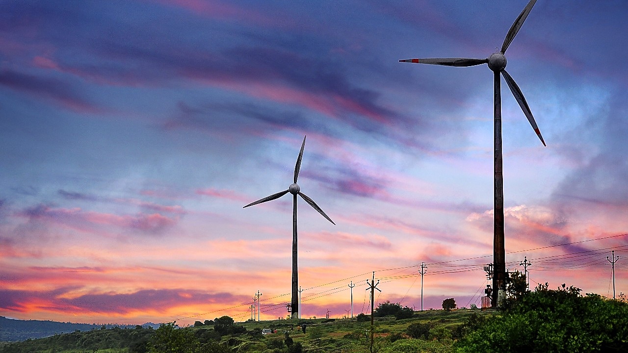
{Wind turbines. Colourful sunset.}
[Test displays]
Power
[Voiceover]
Power
[Animated sequence]
{Male leaning over row of solar panels. Wind turbines in the background.}
[Test displays]
Renewables and carbon credits
Building a better energy future
[Voiceover]
And Renewables and carbon credits. Building a better energy future.
[Animated sequence]
{Shell Energy Lockup appears}

Natural gas and LNG
Shell has over 50 years of experience as a producer of natural gas and today it is one of the world’s leading producers.
Across Asia, Shell Energy has significant experience trading and marketing gas to help meet the energy needs of our customers.
Business energy services
Access a range of energy products and services that can power your business when and where you need them.
Why choose Shell Energy
By combining our global reach with our on-the-ground expertise, you can get the flexibility and support to build the right partnership for you.
Case studies
In India and around the world Shell are helping businesses meet their energy needs and supporting them on their decarbonisation journeys by providing innovative, reliable and cleaner energy solutions through a portfolio of gas, power, carbon products and energy efficiency solutions.
Explore our case studies below to learn more about our customer collaborations and discover how we can make progress together.

Helping AG&P Pratham build a virtual pipeline to supply natural gas to off-grid customers India
Contact us

